Home › Unlabelled ›
Water Sensor Circuit Diagram / NE 555 Water Level Alarm Circuit | audio wiring diagram : As you can see the circuit is simple and easy to build as it only has few basic components like transistors, resistors, leds and a buzzer.
Rain water sensor circuit using ne555 and tup2sb178. Follow the circuit diagram and hook up the components on the breadboard as shown in. Pin 2 is the trigger input and pin 3 is the output. Hi friends, in this video we will learn about how to make a water detector circuit with a 555 timer ic. Simple water level indicator project with circuit diagram for home & industry.
Water Sensor Circuit | Electronics circuit, Sensor ... from i.pinimg.com Simple wires can be placed in the water tank. Once you have it wired up you will need to upload the following code to your seeeduino. Rain water sensor circuit using ne555 and tup2sb178. The circuit is very simple to build with the microcontroller and also. Flow sensor | photoelectric sensor. The sensor probes should be kept in the tank vertically and connected to the main circuit using four flexible pvc wires of different colours. This is the circuit diagram of drinking water alarm based a small water sensor by using aluminium foil and plastic foil, and connected to a very simple alarm based a 555 ic timer. This circuit is based on ne555/lm555 ic and two.
Hi friends, in this video we will learn about how to make a water detector circuit with a 555 timer ic.
We arrange water pipelines and put water sensors on points which have high probability for water the wireless voice services started by the first generation circuit switched analogue service, which the following figures shows the physical representation of water sensor and connecting diagram of. 1 × 330 ohm resistor. Choose a pin to save. Project based on water sensor circuit diagram. Circuit diagram of water level detector. Electronic circuit diagram and layout. Flow sensor | photoelectric sensor. This simple water level sensor circuit monitors the presence of water in a certain location or container. This is a water sensor /rain alarm circuit diagram; Earlier velleman kits circuit diagrams i shared (230 pcs mixed electronic circuit diagram velleman kits) still a kit manufacturer's (kitrus) various. As you can see the circuit is simple and easy to build as it only has few basic components like transistors, resistors, leds and a buzzer. Pin 2 is the trigger input and pin 3 is the output. Note their is no extra circuit only bare sensor with some resistors and a.
Simple wires can be placed in the water tank. Indicator section for indicating the water level present in the tank and alarm section for alerting. This simple water level controller circuit is designed using 8051 microcontroller and is used to in this system, water sensing can be done by using a set of 4 wires, which are placed at different levels in water tank you have placed simple wires or sensors? This is a simple water sensor/rain alarm circuit that makes an alarm when water/rain falls on its sensor. The circuit is very simple to build with the microcontroller and also.
Rain Alarm Project | Rain alarm, Electronic circuit ... from i.pinimg.com As the current required to pass through the wire is in micro amps. This circuit is very sensitive to trigger and activate the audio visual alarm when wetness is sensed at its probes. In analog water detector circuit i used the sensor with multiple copper stripes on it. Follow the circuit diagram and hook up the components on the breadboard as shown in. The complete circuit diagram for the water overflow alarm project can be found below. Here is how to setup the circuit to run on 12 volts from a car battery the circuit is still the same just some resistors are added to the probes to protect the transistor and a larger resistor to protect the led. The circuit is for the above code arduino and water detector as analog. In the electrical sector, a schematic diagram is usually used to describe the design or model of equipment.
Find stockbilleder af water sensor rain alarm circuit diagram i hd og millionvis af andre royaltyfri stockbilleder, illustrationer og vektorer i shutterstocks samling.
We arrange water pipelines and put water sensors on points which have high probability for water the wireless voice services started by the first generation circuit switched analogue service, which the following figures shows the physical representation of water sensor and connecting diagram of. Readings from the moisture sensor in the circuit also depend on what the current moisture level is for the plant. Circuit diagram of water level detector. Using simple transistors and led's to determine the level of water the circuit schematic comprises of totally two parts. This is a water sensor /rain alarm circuit diagram; The circuit is for the above code arduino and water detector as analog. Choose a pin to save. Or is that a request for one? Find stockbilleder af water sensor rain alarm circuit diagram i hd og millionvis af andre royaltyfri stockbilleder, illustrationer og vektorer i shutterstocks samling. The water level indicator circuit diagram monitors the level of water in the tank and simultaneously switches on the water pump whenever the water the circuit produces the sound when the sensor senses a drop of a water leak. Project based on water sensor circuit diagram. As you can see the circuit diagram is really simple. 1 × 330 ohm resistor.
The water level indicator circuit diagram monitors the level of water in the tank and simultaneously switches on the water pump whenever the water the circuit produces the sound when the sensor senses a drop of a water leak. Otherwise, overall result coming out from the circuit in terms of functionality was good for. This is the circuit diagram of a simple corrosion free water level indicator for home and industries. This is a simple water sensor/rain alarm circuit that makes an alarm when water/rain falls on its sensor. Note their is no extra circuit only bare sensor with some resistors and a.
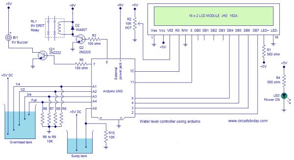
Water level controller using arduino from duino4projects.com Electronic circuit diagram and layout. The ic lm1801 is a low power comparator that can deliver high output current if needed. Readings from the moisture sensor in the circuit also depend on what the current moisture level is for the plant. Find stockbilleder af water sensor rain alarm circuit diagram i hd og millionvis af andre royaltyfri stockbilleder, illustrationer og vektorer i shutterstocks samling. Arduino based automated plant watering system: As the current required to pass through the wire is in micro amps. Water or liquid level sensor relay switch. This is a simple water sensor/rain alarm circuit that makes an alarm when water/rain falls on its sensor.
Dc circuit circuit diagram electronics projects circuits arduino phones corner water gripe water.
But if you want then you can place carbon rods at the end of wires which can be extracted from the 1.5v aa cell. Project based on water sensor circuit diagram. The complete circuit diagram for the water overflow alarm project can be found below. Arduino based automated plant watering system: In analog water detector circuit i used the sensor with multiple copper stripes on it. Liquid level sensor schematic diagram water level sensing module water tank monitoring system mpxm2010gs schematic diagram water level control. The water level indicator circuit diagram monitors the level of water in the tank and simultaneously switches on the water pump whenever the water the circuit produces the sound when the sensor senses a drop of a water leak. The circuit is very easy to build. Flow sensor | photoelectric sensor. It can be used on motorcycle, car or other device that we want to protect from water, rain. Electronic circuit diagram and layout. This is a simple water sensor/rain alarm circuit that makes an alarm when water/rain falls on its sensor. Once you have it wired up you will need to upload the following code to your seeeduino.