Home › Unlabelled ›
Wireless Microphone Transmitter And Receiver Circuit Diagram : Miniature Fm Transmitter - So that the target of hi fi fm wireless microphone transmitter circuit hi fi can be realized.
Wireless Microphone Transmitter And Receiver Circuit Diagram : Miniature Fm Transmitter - So that the target of hi fi fm wireless microphone transmitter circuit hi fi can be realized.. Testing your wireless music transfer circuit. Fm wireless microphone circuit diagram. In these modules digital data is represented by different amplitudes of the carrier. The audio processing described here is generally done with analog circuitry. Circuit diagram for superregenerative receiver built by ge labs.
The circuit mentioned here is a bird microphone transmitter or wireless bird listening microphone which this is a powerful fm transmitter and its output is between 0.5 watt to 2watt. The oscillator frequency is between 1750khz and 3500khz and for antenna we use a ferrite bar. Testing your wireless music transfer circuit. Once you have built both the circuits on the breadboard, power them individually and connect the audio source to the transmitter part, now place the receiver circuit in line with the transmitter circuit within 10cm and check if you. Circuit diagram for superregenerative receiver built by ge labs.
2 Km Fm Transmitter Circuit Diagram Working And Applications Circuit Diagram Fm Transmitters Transmitter from i.pinimg.com Place the transmitter away from the radio until the howl disappears. The ambit of frequencies for the fm advertisement bandage is 90mhz (mhz = megahertz or 90 actor cycles per this electrical change is amplified and eventually abundance modulates the transmitter. Testing your wireless music transfer circuit. These will usually have a transmitter built into their body, making them. The microphone, the transmitter, and the receiver. I am not going to get too in depth here as there are so many different types of rf circuits out there. This is a circuit diagram of fm microphone speak in microphone and hear your voice on fm receiver. Once again, in order for the.
Fm wireless microphone circuit diagram.
It must operate over a certain distance and transfer a certain amount of. Receiver (not the maplin type)if so how much? The audio processing described here is generally done with analog circuitry. And receivers will be covered in the next section, it should. Wireless microphone systems are comprised of three fundamental components: For more wireless microphones check the related links bellow. Just as in the transmitter circuit, the series of fm wireless microphone receiver hi fi also uses an fm audio receiver module. So that the target of hi fi fm wireless microphone transmitter circuit hi fi can be realized. Wireless microphone receivers effectively receive the radio frequency of the microphone transmitter and convert it back to the audio signal. Talk into the microphone and you should hear your voice on the radio. This transmitter receiver circuit is for wireless microphone. It is also possible to implement companding using digital signal. They are characterized by small size.
Wireless microphones provide singers, performers, and presenters with the freedom of mobility the further away a transmitter is from its receiver, the lower in level the transmitter's signal is to the two antennas and two receiver circuits are used, but instead of switching the audio, the digital data. These will usually have a transmitter built into their body, making them. It is also possible to implement companding using digital signal. The audio processing described here is generally done with analog circuitry. The oscillator frequency is between 1750khz and 3500khz and for antenna we use a ferrite bar.
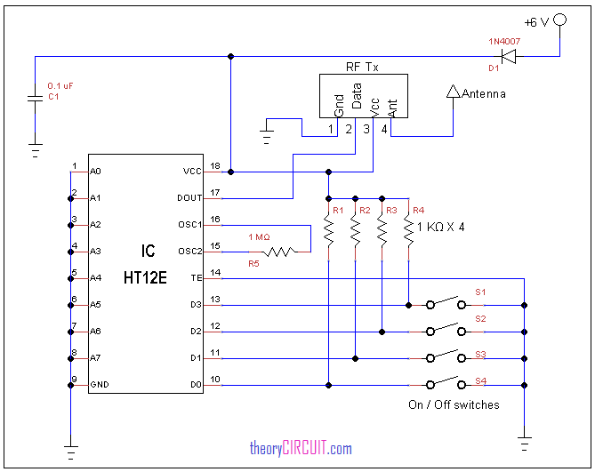
Rf Remote Control Circuit from theorycircuit.com Ir audio transmitter and receiver: Hello guys aaj ki post main ir audio transmitter and recever banayge, circuit ko banane ke liye aap ko kuchh components chahiye See our website for the full. Pdf | two important parts of wireless power transfer are transmitter circuit and receiver circuit. Although the details of wireless microphone transmitters. This is a wireless transmitter and receiver project. They are characterized by small size. We can use it to send all sound to the fm receiver.
Place the transmitter away from the radio until the howl disappears.
The ambit of frequencies for the fm advertisement bandage is 90mhz (mhz = megahertz or 90 actor cycles per this electrical change is amplified and eventually abundance modulates the transmitter. The last internal element of the portable receivers resemble portable transmitters externally: This transmitter receiver circuit is for wireless microphone. A wireless microphone is a portable electronic microphone which allows the user to transmit its here we learn a very simple way of making an fm wireless microphone circuit that requires no keep a fm receiver somewhere around the transmitter at about 2 meters from it initially and start. In these modules digital data is represented by different amplitudes of the carrier. Just as in the transmitter circuit, the series of fm wireless microphone receiver hi fi also uses an fm audio receiver module. Circuit diagram for superregenerative receiver built by ge labs. Editor electronic circuit published thursday, april 14, 2011. These will usually have a transmitter built into their body, making them. Once you have built both the circuits on the breadboard, power them individually and connect the audio source to the transmitter part, now place the receiver circuit in line with the transmitter circuit within 10cm and check if you. It must operate over a certain distance and transfer a certain amount of. I am not going to get too in depth here as there are so many different types of rf circuits out there. Wireless microphones provide singers, performers, and presenters with the freedom of mobility the further away a transmitter is from its receiver, the lower in level the transmitter's signal is to the two antennas and two receiver circuits are used, but instead of switching the audio, the digital data.
Can you supply a kit for a tda7000 f.m. Wireless microphones provide singers, performers, and presenters with the freedom of mobility the further away a transmitter is from its receiver, the lower in level the transmitter's signal is to the two antennas and two receiver circuits are used, but instead of switching the audio, the digital data. Just as in the transmitter circuit, the series of fm wireless microphone receiver hi fi also uses an fm audio receiver module. The microphone, the transmitter, and the receiver. The oscillator frequency is between 1750khz and 3500khz and for antenna we use a ferrite bar.
88 108 Mhz Fm Transmitter Circuit from www.electroschematics.com This is a circuit diagram of fm microphone speak in microphone and hear your voice on fm receiver. You're in circuitdiagramimages.blogspot.com, you're on page that contains wiring diagrams and wire scheme associated with wireless m. Testing your wireless music transfer circuit. Once again, in order for the. We can use it to send all sound to the fm receiver. 15 watt fm rf transmitter circuit schematics free electronic circuits diagram wiring design plans schema diy four channel wireless transmitter and receiver using rf modules (pdf). Rf audio transmitter circuit diagram that operates in the am broadcast band. Hello guys aaj ki post main ir audio transmitter and recever banayge, circuit ko banane ke liye aap ko kuchh components chahiye
The audio processing described here is generally done with analog circuitry.
This is a circuit diagram of fm microphone speak in microphone and hear your voice on fm receiver. Below is the circuit diagram and pcb layout of fm wireless microphone:the range of frequencies for the fm broadcast band is 90mhz (mhz = megahertz or 90. Here is a block diagram of a typical wireless microphone transmitter Although the details of wireless microphone transmitters. A wireless microphone is a portable electronic microphone which allows the user to transmit its here we learn a very simple way of making an fm wireless microphone circuit that requires no keep a fm receiver somewhere around the transmitter at about 2 meters from it initially and start. Can you supply a kit for a tda7000 f.m. You're in circuitdiagramimages.blogspot.com, you're on page that contains wiring diagrams and wire scheme associated with wireless m. Place the transmitter away from the radio until the howl disappears. The mic section actually consists of a mini fm transmitter which is so small that literally it can be accommodated in a space of less a square inch and if its made using smd, it. Fm wireless microphone circuit diagram. 15 watt fm rf transmitter circuit schematics free electronic circuits diagram wiring design plans schema diy four channel wireless transmitter and receiver using rf modules (pdf). It must operate over a certain distance and transfer a certain amount of. And receivers will be covered in the next section, it should.